|
ELECTRICAL SHOCK PROTECTION
Each luminaire is insulated so that any exposed metal parts do not carry electrical current. Parts that carry current during
normal operation must be protected against contact either by insulation or a suitable cover. Additional measures are taken to prevent exposed
metal parts carrying current even if an insulation fault occurs. |
 |
Class I |
Luminaires with a terminal for a protective conductor to which all metal parts that could carry current in the event of a
fault must be connected. Connection to a protective earth conductor absolutely essential. The symbol is displayed on the terminal. |
 |
Class II |
There must be no exposed metal parts that could carry current in the event of a fault
(total insulation or double insulation). The luminaire does not have to have a protective conductor terminal and does not have to be connected
to a protective earth conductor. |
 |
Class III |
Luminaires to be operated with safety extra-low voltage (SELV), i.e. voltages under 50 V generated with a safety
transformer to VDE 0551 or supplied by batteries (standard or rechargeable) |
IGNITION / FIRE PROTECTION
When operated, luminaires generate heat. The following symbols are used for luminaires that can be mounted on flammable materials. |
 |
|
Luminaires are suitable for direct mounting on normally flammable materials, in which
you may not exceed 130°C (in normal operation) and 180°C (in fault case) for less than 15 min. |
 |
|
Luminaires are suitable for direct mounting on materials that have normal or reduced
flammability, in which you may not exceed 95°C (in normal operation), 130°C (in annormal operation) and 180°C (in fault case) for
less than 15 min.. Maximum temperature on the mounting surface: 130 °C. |
 |
|
Luminaires are suitable for direct mounting on materials for which the flammability properties are not known, in which you may not
exceed 95°C (in normal operation) and 115°C (in abnormal operation fault case). |
IP - INGRESS PROTECTION
Dust, solid materials and water protection. Luminaires must belong to a particular protection class against moisture and dust to which they are exposed.
The lowest protection class is "covered"; in other words, the luminaires have no protection against moisture or dust but are covered in such a way
that it is impossible to touch electric parts without using a tool. Luminaires without any indication of a protection class are classified as IP20. |
| |
|
First digit: Level of protection against particules |
| |
IP1x |
Protected against solid objects greater than 50 mm |
| |
IP2x |
Protected against solid objects greater than 12 mm |
| |
IP3x |
Protected against solid objects greater than 2,5 mm |
| |
IP4x |
Protected against solid objects greater than 1 mm |
 |
IP5x |
Dust-proof. Permits dust to enter to the extent that will not effect the operation of the luminaire |
 |
IP6x |
Dust-tight. Completely protects against the entry of any dust |
| |
|
Second digit: Level of protection against water |
| |
IPx1 |
Drip-proof. Not Subject to adverse effect from drips of water that comes perpendicularly |
| |
IPx2 |
Drip-proof. Not Subject to adverse effect from drips of water that comes within the range of 15° from the perpendicular |
 |
IPx3 |
Rain-proof. Protection against water falling at any angle up to 60° |
 |
IPx4 |
Splash-proof. Protection against water sprayed at any angle at the luminaire |
 |
IPx5 |
Jet-proof. Not Subject to adverse effect from direct jet of water that comes in any direction |
| |
IPx6 |
Water-resistant. Protection against a jet of water directed at the luminaire at any angle |
 |
IPx7 |
Waterproof (immersible). Protection against water if the luminaire is submerged in water under defined time and pressure conditions |
 |
IPx8 |
Pressure-watertight (submersible). The luminaire is suitable for permanent submerging in water under conditions defined by the manufacturer |
| |
|
Level of protection against access to hazardous parts by persons |
| |
A |
backside of hand, tested by a ball d=50mm |
| |
B |
finger, tested by a probe d=12mm and l=80mm |
| |
C |
tool, tested by a probe d=2.5mm and l=100mm |
| |
D |
wire, tested by a probe d=1mm and l=100mm |
| |
|
Other indicators |
| |
H |
high voltage device |
| |
M |
device moving during water test |
| |
S |
device standing still during water test |
| |
W |
weather conditions |
IK - PROTECTION AGAINST MECHANICAL IMPACTS
The aptitude of equipment to resist mechanical impacts on all sides.
|
| | IK00 | no protection |
| | IK01 | 0.14 joule impact |
| | IK02 | 0.20 joule impact |
| | IK03 | 0.35 joule impact |
| | IK04 | 0.50 joule impact |
| | IK05 | 0.70 joule impact |
| | IK06 | 1 joule impact (500 gr from 20cm) |
| | IK07 | 2 joule impact (500 gr from 40cm) |
| | IK08 | 5 joule impact (1.7 kg from 29cm) |
| | IK09 | 10 joule impact (5 kg gr from 20cm) |
| | IK10 | 20 joule impact (5 kg from 40cm) |
Ex - PROTECTION AGAINST EXPLOSION
|
 |
|
Example:  II 2 GD EEx d IIB 85°C T6 II 2 GD EEx d IIB 85°C T6 |
|
II |
Equipment group.
I : for use in mines
II: surface industries |
|
2 |
Category of protection.
1 : Can be used in zone 0 or 20
2 : Can be used in zone 1 or 21
3 : Can be used in zone 2 or 22
A place in which an explosive atmosphere consisting of a mixture with air of flammable substances
in the form of gas, vapour or mist is;
Zone 0 present continuously or for long periods or frequently.
Zone 1 likely to occur in normal operation occasionally.
Zone 2 not likely to occur in normal operation but, if it does occur, will persist for a short period only.
A place in which an explosive atmosphere in the form of a cloud of combustible dust in air is;
Zone 20 present continuously, or for long periods or frequently.
Zone 21 likely to occur in normal operation occasinoally.
Zone 22 not likely to occur in normal operation but, if it does occur, will persist for a short period only. |
|
GD |
Atmosphere.
G : tested for gases
D : tested for dusts |
|
EEx |
means equipment tested under the latest European Harmonised Standard for use in Explosive atmospheres. |
|
d |
Type of protection against ignition.
e : Increased Safety (to prevent any means of ignition arising)
nA: Non Sparking (to prevent any means of ignition arising)
i : Intrinsic Safety (to limit the ignition energy of the circuit)
nL: Energy limitation (to limit the ignition energy of the circuit)
m : Encapsulation (to prevent the explosive mixture reaching a means of ignition)
p : Pressurisation (to prevent the explosive mixture reaching a means of ignition)
o : Oil immersion (to prevent the explosive mixture reaching a means of ignition)
nR: Restricted Breathing (to prevent the explosive mixture reaching a means of ignition)
d : Flameproof Enclosure (to prevent any ignition from spreading outside of the apparatus)
q : Powder Filling (to prevent any ignition from spreading outside of the apparatus)
nC: Non incendive (to prevent any ignition from spreading outside of the apparatus) |
|
IIB |
Explosion group (specified only for equipment to be used in explosive gas atmospheres)
I : All underground Coal Mining applications) Firedamp (methane)
IIA: Industrial methane, propane, petrol and the majority of industrial gases
IIB: Ethylene, coke oven gas and other industrial gases
IIC: Hydrogen, acetylene, carbon disulphide |
|
85°C |
Maximum surface temperature. |
|
T6 |
Temperature classification.
Hot surfaces can ignite explosive atmospheres. To guard against this all Electrical Equipment intended for use in a potentially explosive
atmosphere is classified according to the maximum
surface temperature it will reach in service. This temperature is normally based on a surrounding ambient temperature of 40 degrees Centigrade.
This temperature can then be compared to
the ignition temperature of the gas(es) which may come into contact with the equipment and a judgement reached as to the suitability of the
equipment to be used in that area. |
|
|
Temperature
class |
Permissible surface temperature
of the electrical equipment |
| T1 | 450 °C |
| T2 | 300 °C |
| T3 | 200 °C |
| T4 | 135 °C |
| T5 | 100 °C |
| T6 | 85 °C |
|
| OTHER SIGNS |
 |
|
Maximum surrounding temperature |
 |
|
Minimum distance from the lighted surface |
 |
|
GREEN DOT, means that the manufacturer of the product contributes to the cost of
recovery and recycling. This can be with household waste collected by the authorities, or in containers in public places.
The system is financed by a green dot licence fee paid by the producers of the products. Fees vary by country and are based on the material
used in packaging (eg paper, plastic, metal, wood, cardboard). Each country also has different fees for joining the scheme and ongoing fixed
and variable fees. Fees also take into account the cost of collection, sorting and recycling methods.
In short, the system encourages manufacturers to cut down on packaging as this saves them the cost of licence fees.
|
CERTifICATE MARKS
Indicates conformity to standarts of a luminaire. |
 |
ENEC |
European Norms Electrical Certification which is recognized by all European approbation authorieties.
The number following the sign indicates the country of certification, i.e. 10 - Germany, 11 - Austria, 13 - Switzerland, ... |
 |
CE |
With CE certificate a manufacturer declares the conformity of his products with European guidelines without tests from an independent organisation.
The low voltage guideline and the EMV guideline for electromagnetic compatibility guidelines apply to luminaires. This guideline contains only
general requirements, no details like the European standards. |
 |
VDE |
(Association of German Electrotechnical Engineers) is carrier of the independant German test and certification institute.
Products with VDE approval mark are electrically safe, mechanically safe, thermally safe, standard compliant and supervised by VDE during production |
 |
VDE-EMV |
sign stands for electro-magnetic compatibility, i.e the interference and
interference resistance of the appliances. It also signals that the products function reliably in electro-magnetic environments |
 |
TUV GS |
Europe-wide recognised German Safety certificate. Use of the GS Mark demonstrates that the electrical safety of the product has been independently verified |
 |
DEMKO |
Danish mark |
 |
FIMKO |
Finish mark |
 |
IMQ |
Italian mark |
 |
NEMKO |
Norwegian mark |
 |
SEMKO |
Swedish mark |
 |
SEV |
Swiss mark |
 |
UkrSEPRO |
Ukranian mark |
 |
GOST |
Russian mark |
 |
TSE |
Turkish mark |
 |
CCC |
Chinese mark |
 |
C TICK |
Australian mark |
|
|
 Lamp Guide: Everything you want to know about bulbs.
(649 Kb pdf file prepared by Lighting Industry Federation Limited, UK)
Lamp Guide: Everything you want to know about bulbs.
(649 Kb pdf file prepared by Lighting Industry Federation Limited, UK)
|
| INCANDESCENT |
|
|

 When solids and liquids are heated, they emit visible radiation at temperatures above 725 C; this is known as incandescence.
This heating is the basis of light generation in filament bulbs. An electrical current passes through a thin tungsten wire, whose temperature rises
to around 3000 C and it glows.
When solids and liquids are heated, they emit visible radiation at temperatures above 725 C; this is known as incandescence.
This heating is the basis of light generation in filament bulbs. An electrical current passes through a thin tungsten wire, whose temperature rises
to around 3000 C and it glows.
Tungsten filament bulbs are used mainly for domestic and display lighting. The most common of them is GLS (General Lighting Service).
• SOCKETS: E14 (3-60w), E27 (11-120w), E39 (300-500w), GX16d (300w)
• LABELS: GLS / INC / R
• PROS: low initial cost, excellent color rendering, easy installation, without control gear, instantly lights.
• CONS: very low efficacy (lumen/watt), very short life, sensitive to voltage variations, sensitive to vibration, high heat disipation (85 btu/hr). |
| HALOGEN |
|
|

 A halogen lamp is an incandescent lamp with a tungsten filament contained within an inert gas and a small amount of a halogen such as iodine or bromine.
The combination of the halogen gas and the tungsten filament produces a chemical reaction known as a halogen cycle which increases the lifetime of the
filament and prevents darkening of the bulb by redepositing tungsten from the inside of the bulb back onto the filament. Because of this, a halogen lamp
can be operated at a higher temperature than a standard gas-filled lamp of similar power and operating life. The higher operating temperature results in
light of a higher color temperature.
A halogen lamp is an incandescent lamp with a tungsten filament contained within an inert gas and a small amount of a halogen such as iodine or bromine.
The combination of the halogen gas and the tungsten filament produces a chemical reaction known as a halogen cycle which increases the lifetime of the
filament and prevents darkening of the bulb by redepositing tungsten from the inside of the bulb back onto the filament. Because of this, a halogen lamp
can be operated at a higher temperature than a standard gas-filled lamp of similar power and operating life. The higher operating temperature results in
light of a higher color temperature.
• PROS: higher efficacy (10–30 lm/W) and extended life compared to incandescent bulbs, small size, good color rendering, instantly lights.
• CONS: very high heat disipation, may require control gear, sensitive to voltage variations.
• LABELS: HAL / TH / MR / PAR
• SOCKETS: E14 (18-42w), E27 (18-140w), E40 (500-2000w), G4 (5-30w), G5.3 (30-360w), G53 (30-100w), G6.35 (50-650w), G22 (650-2500w), G38 (1000-5000w),
G9 (18-60w), G9.5 (575-1000w), GU4 (14-35w), GU5.3 (14-75w), GU10 (18-60w), GX5.3 (25-340w), GX6.35 (150-300w), GX9.5 (650-1200w), GY16 (2000w),
GY6.35 (20-300w), GY9.5 (300-1000w), GZ10 (50w), GZ4 (9-75w), GZ6.35 (42-150w), GZ9.5 (95-150w), R7s (48-1500w), RX7s (150-2000w)
|
| LINEAR FLUORESCENT |
|
|
 Low pressure mercury fluorescent tubes. The light output comes from phosphors that convert energy from a low pressure gas
discharge into visible light. Fluorescence occurs when an electrical charge passes through the gas-filled tube. The charge excites the gas,
causing it to emit invisible radiation, which then reacts with a phosphor coating inside the tube to produce a glow.
Low pressure mercury fluorescent tubes. The light output comes from phosphors that convert energy from a low pressure gas
discharge into visible light. Fluorescence occurs when an electrical charge passes through the gas-filled tube. The charge excites the gas,
causing it to emit invisible radiation, which then reacts with a phosphor coating inside the tube to produce a glow.
The Color temperature and Color rendering are determined by the phosphor mix coated on the inside of the tube. The argon-filled T12 (38mm dia)
tubes are being discontinued.
The new range of krypton-filled triphosphor T8 (26mm) dia tubes have a higher efficiency, longer life, improved lumen maintainance and better
Color rendering than earlier types.
• SOCKETS: 2G13 (18-58w), 2GX13 (28-60), FA6 (15-65w), FA8 (30-75w), G10q (20-40w), G13 (10-84w), G85 (4-80w), GX5 (95-120w), R17d (35-215w), R18s (20-40w)
• LABELS: LFL / T2 / T5 / T8 / T12
• PROS: higher efficiency and longer life compared to filament bulbs, wide range of color temperatures, low bulb surface temperature, average
heat dissipation (30 btu/hr).
• CONS: requires control gear, magnetic gears may be noisy and may flicker the bulb, higher installation cost compared to incandescent
bulbs, environmental impact: contains the very toxic Mercury. |
| COMPACT FLUORESCENT |
|
|

 Self-supporting fluorescent bulb with a single base. A compact fluorescent bulb has the characteristics and advantages of
linear fluorescent bulbs. Its compact size is achieved by using smaller diameter bended tubes and a single socket base.
Self-supporting fluorescent bulb with a single base. A compact fluorescent bulb has the characteristics and advantages of
linear fluorescent bulbs. Its compact size is achieved by using smaller diameter bended tubes and a single socket base.
• SOCKETS: E14 (3-13w), E27 (3-65w), E40 (75-80w), GU10 (7-10w), GU24 (13-23w), GX53 (7-9w),
2G11 (18-80w), 2G7 (5-11w), G23 (5-11w), G24d-1 (10-13w), G24d-2 (18w), G24d-3 (26w), G24q-1 (10-13w), G24q-2 (14-18w), G24q-3 (21-26w), GR10q (16-38w),
GR8 (16-28w), GX23 (13w), GX24q-1 (13-38w), GX24q-2 (18w), GX24q-3 (21-32w), GX24q-4 (33-42w), GX24q-5 (27-57w)
• LABELS: CFL
• PROS: same as of linear fluorescent bulbs plus; compact size compared to them, easy conversion and installation using bulbs with integrated gear (allows the
use of incandescent sockets).
• CONS: may require a control gear, higher installation cost compared to incandescent bulbs, high bulb cost, environmental impact: contains the very toxic Mercury. |
| LIGHT EMITTING DIODE (LED) |
|
|

 The LED is a semi conducting device generating light by means of electric charges flowing through a silicon joint which has
been properly treated. The LED is therefore a diode which starts to emit light when it reaches its threshold potential (about 3.5V).
Light emitting diodes have been used for indicating purposes for several decades. Nowadays, larger diodes with more lightpower and extended
Colors are used for lighting purposes.
The LED is a semi conducting device generating light by means of electric charges flowing through a silicon joint which has
been properly treated. The LED is therefore a diode which starts to emit light when it reaches its threshold potential (about 3.5V).
Light emitting diodes have been used for indicating purposes for several decades. Nowadays, larger diodes with more lightpower and extended
Colors are used for lighting purposes.
• SOCKETS: E14 (2-3w), E27 (3-18w), G4 (2.5w), G13 (13-25w), G53 (10-15w), GU5.3 (4-10w), GU10 (3-7w), B22 (7-12w)
• LABELS: LED
• BRANDS: Philips - LUXEON, Osram - OSTAR, Cree - XLAMP
• PROS: extremely long life, very low heat dissipation (3 btu/hr), very small size, very efficient, any color output without filters (RGB),
not sensetive to shock and vibration, no UV radiation, very little heat in the form of IR that can cause damage to sensitive objects like artwork or fabrics (wasted energy is
dispersed as heat through the base of the LED), heat output of a LED will not cause fire, the low ambient temperature will
increase the light output slightly and prolong the life of the LED
• CONS: requires control gear, high initial cost, blue LEDs and cool-white LEDs are now capable of exceeding safe limits of the so-called
blue-light hazard as defined in eye safety specifications such as ANSI/IESNA RP-27.1–05: Recommended Practice for Photobiological Safety for Lamp
and Lamp Systems, cool-white LEDs can cause more light pollution than other light sources (cool-white LEDs emit proportionally more blue light
than conventional outdoor light sources) |
| HIGH INTENSITY DISCHARGE (HID) |
|
|
| High Intensity Discharge technology replace the filament of the light bulb with a capsule of gas. The light is produced by
passing a current through a metal vapor by an arc
discharge between two closely spaced electrodes inside a small quartz glass tubular capsule. The amount of light produced is greater than a
standard halogen bulb, while consuming less power,
and more closely approximating the color temperature of natural daylight. It produces ~5% of its output when first ignited and requires some
time to come up to full output.
Mercury vapor, metal halide, low/high pressure sodium bulbs are members of HID family. |
| METAL HALIDE |
|
|

 Metal halide bulbs have quartz or sintered alumina (ceramic) arc tubes, generally with an outer glass envelope.
Light output is from mercury and other metallic elements introduced in the form of halides. Metal halide bulbs of the ‘protected’ type are now
available for operation in luminaries without safety screens.
According to the mix of elements, there is a wide range of efficacy and/or color appearance, but color rendering is generally good.
Metal halide bulbs are generally used in commercial interiors, industry and floodlighting, and for retail lighting in some cases.
They have bluish white output.
Metal halide bulbs have quartz or sintered alumina (ceramic) arc tubes, generally with an outer glass envelope.
Light output is from mercury and other metallic elements introduced in the form of halides. Metal halide bulbs of the ‘protected’ type are now
available for operation in luminaries without safety screens.
According to the mix of elements, there is a wide range of efficacy and/or color appearance, but color rendering is generally good.
Metal halide bulbs are generally used in commercial interiors, industry and floodlighting, and for retail lighting in some cases.
They have bluish white output.
• LABELS: MH / MBI / MHN / HIE / HIT/ HCI / HQI / HPI
• PROS: long life, very efficient, good color rendering
• CONS: requires control gear, high initial cost, long start-up time, very long restrike time |
| LOW PRESSURE SODIUM |
|
|
 Low pressure sodium bulbs consist of a U tube containing the discharge, and an outer heat reflecting glass jacket.
The monochromatic light is concentrated in the yellow part of the visible spectrum which is close to the maximum sensitivity of the human eye at
normal lighting levels.
The efficacy is the highest of all bulb types, but with very poor Color rendering. Low pressure sodium bulbs are used mainly for exterior
applications such as road and security lighting (but are not suitable for repeated on/off (operation).
Low pressure sodium bulbs consist of a U tube containing the discharge, and an outer heat reflecting glass jacket.
The monochromatic light is concentrated in the yellow part of the visible spectrum which is close to the maximum sensitivity of the human eye at
normal lighting levels.
The efficacy is the highest of all bulb types, but with very poor Color rendering. Low pressure sodium bulbs are used mainly for exterior
applications such as road and security lighting (but are not suitable for repeated on/off (operation).
• LABELS: LPS / SOX
• PROS: long life, extremely efficient, very poor Color rendering
• CONS: requires control gear, very high initial cost, long start-up time |
| HIGH PRESSURE SODIUM |
|
|

 Light is generated by an electrical discharge in a gas containing sodium and mercury (sodium amalgam) contained in a sintered
alumina arc-tube. High pressure sodium bulbs are used for road lighting, floodlighting and industrial interior lighting. They have yellow-orange output.
The pressure of the High Pressure Sodium bulbs is less than one atmosphere, but they are so called to distinguish them from Low Pressure Sodium bulbs.
Light is generated by an electrical discharge in a gas containing sodium and mercury (sodium amalgam) contained in a sintered
alumina arc-tube. High pressure sodium bulbs are used for road lighting, floodlighting and industrial interior lighting. They have yellow-orange output.
The pressure of the High Pressure Sodium bulbs is less than one atmosphere, but they are so called to distinguish them from Low Pressure Sodium bulbs.
• LABELS: HPS / SON / HSE / HST
• PROS: very long life, extremely efficient, poor Color rendering
• CONS: requires control gear, very high initial cost, long start-up time |
| MERCURY VAPOR |
|
|
 • LABELS: MV / HPL / HQL
• PROS: very long life, good Color rendering
• CONS: requires control gear, very high initial cost, long start-up time |
| HIGH PRESSURE MERCURY |
|
|
 Mercury bulbs were used for illuminating road signs and industrial lighting but have largely been
replaced by the more efficient bulbs now available. Such bulbs offer low cost discharge lighting where high efficency is not important.
They often incorporate a third electrode for starting and in such cases the control gear required generally consists only of a ballast
and a power-factor corrected capacitor.
Mercury bulbs were used for illuminating road signs and industrial lighting but have largely been
replaced by the more efficient bulbs now available. Such bulbs offer low cost discharge lighting where high efficency is not important.
They often incorporate a third electrode for starting and in such cases the control gear required generally consists only of a ballast
and a power-factor corrected capacitor.
• LABELS: HME / MVL / MBF / HML
|
| MERCURY-TUNGSTEN BLENDED |
|
|
 Mercury tungsten blended bulbs are mercury bulbs whose ballast is a tungsten filament located between the two envelopes.
The tungsten filament acts as an incandescent bulb and replaces ballast.
Mercury tungsten blended bulbs are mercury bulbs whose ballast is a tungsten filament located between the two envelopes.
The tungsten filament acts as an incandescent bulb and replaces ballast.
• LABELS: MVL-SB
• PROS: control gear not required,
• CONS: poor color rendering |
| HYDRARGYRUM MEDIUM-ARC IODIDE |
|
|
• LABELS: HMI
|


|
| INDUCTION |
|
|
 Induction is a process whereby electrical power is passed from one circuit to another without the use of physical electrical conductors.
It enables bulbs to be constructed without the need for wire connections to pass through the glass or quartz envelope. Induction bulbs are available as
low pressure mercury bulbs, using the same triphosphor coating of the inner envelope surface as the familiar fluorescent tubes. The commercially
available range of induction bulbs is limited.
Induction is a process whereby electrical power is passed from one circuit to another without the use of physical electrical conductors.
It enables bulbs to be constructed without the need for wire connections to pass through the glass or quartz envelope. Induction bulbs are available as
low pressure mercury bulbs, using the same triphosphor coating of the inner envelope surface as the familiar fluorescent tubes. The commercially
available range of induction bulbs is limited.
• LABELS: IL / LMT
• BRANDS: General Electric - GENURA, Philips - QL, Osram - ENDURA, Amko Solara - SOLARA, Luxim - LifI
|
BULB COMPARISON CHART (Values are typical and may vary by manufacturer)
| WATTS | LUMENS | LUM./WATT | MINIMUM START TEMP. | SURFACE TEMP. | STARTUP TIME | RESTRIKE TIME | AVG. LifETIME | COLOR TEMP. | CRI |
| INCANDESCENT |
| 40w | 480 | 12 | -40°C | >150°C | instant | instant | 1,000 h | 2700k | 100 |
| 60w | 890 | 15 | -40°C | >150°C | instant | instant | 1,000 h | 2700k | 100 |
| 75w | 1,200 | 16 | -40°C | >150°C | instant | instant | 1,000 h | 2700k | 100 |
| 100w | 1,700 | 17 | -40°C | >150°C | instant | instant | 1,000 h | 2700k | 100 |
| 150w | 2,550 | 17 | -40°C | >150°C | instant | instant | 1,000 h | 2700k | 100 |
| TUNGSTEN HALOGEN |
| 35w | 900 | 26 | -40°C | >150°C | instant | instant | 3,500 h | 3000k | 100 |
| 50w | 1300 | 26 | -40°C | >150°C | instant | instant | 3,500 h | 3000k | 100 |
| 65w | 1,700 | 26 | -40°C | >150°C | instant | instant | 3,500 h | 3000k | 100 |
| LED (white) |
| 0.03-20w | | 5-115 | -40°C | <60°C | instant | instant | 35,000 - 50,000 h | 2700-10,000k | 50-90 |
| COMPACT FLUORESCENT |
| 13w | 1,050 | 81 | -20°C | 60-80°C | 0.5 to 5 sec. | 1 sec. | 8,000-16,000 h | 2700-6500k | 60-80 |
| 26w | 1,800 | 69 | -20°C | 60-80°C | 0.5 to 5 sec. | 1 sec. | 8,000-16,000 h | 2700-6500k | 60-80 |
| 32w | 2,400 | 75 | -20°C | 60-80°C | 0.5 to 5 sec. | 1 sec. | 8,000-16,000 h | 2700-6500k | 60-80 |
| 42w | 3,200 | 76 | -20°C | 60-80°C | 0.5 to 5 sec. | 1 sec. | 8,000-16,000 h | 2700-6500k | 60-80 |
| METAL HALIDE |
| 50w | 3,500 | 70 | -20°C | >150°C | 2-5 min. | 10-20 min. | 5,000 h | 4000k | 80-90 |
| 70w | 5,000 | 71 | -20°C | >150°C | 2-5 min. | 10-20 min. | 7,500 h | 4000k | 80-90 |
| 100w | 8,500 | 85 | -20°C | >150°C | 2-5 min. | 10-20 min. | 15,000 h | 4000k | 80-90 |
| 150w | 13,000 | 87 | -20°C | >150°C | 2-5 min. | 10-20 min. | 15,000 h | 4000k | 80-90 |
| 175w | 14,000 | 80 | -20°C | >150°C | 2-5 min. | 10-20 min. | 10,000 h | 4000k | 80-90 |
| 250w | 20,500 | 82 | -20°C | >150°C | 2-5 min. | 10-20 min. | 10,000 h | 4000k | 80-90 |
| LOW PRESSURE SODIUM |
| 18w | 1,800 | 100 | -20°C | | 7-10 min. | 3-12 sec. | 18,000 h | 1700k | 5 |
| 35w | 4,800 | 137 | -20°C | | 7-10 min. | 3-12 sec. | 18,000 h | 1700k | 5 |
| 55w | 7,800 | 142 | -20°C | | 7-10 min. | 3-12 sec. | 16,000 h | 1700k | 5 |
| 131w | 26,200 | 200 | -20°C | 150°C | 7-10 min. | 3-12 sec. | 16,000 h | 1800k | 5 |
| HIGH PRESSURE SODIUM |
| 50w | 4,000 | 80 | -40°C | >150°C | 3-4 min. | 1 min. | 24,000 h | 2200k | 20-30 |
| 70w | 6,300 | 90 | -40°C | >150°C | 3-4 min. | 1 min. | 24,000 h | 2200k | 20-30 |
| 100w | 9,500 | 95 | -40°C | >150°C | 3-4 min. | 1 min. | 24,000 h | 2200k | 20-30 |
| 150w | 16,000 | 107 | -40°C | >150°C | 3-4 min. | 1 min. | 24,000 h | 2200k | 20-30 |
| 250w | 30,000 | 120 | -40°C | >150°C | 3-4 min. | 1 min. | 24,000 h | 2200k | 20-30 |
| MERCURY VAPOR |
| 50w | 1,580 | 32 | -30°C | >80°C | 5-7 min. | 3-6 min. | 24,000 h | 3200-7000k | 50-70 |
| 75w | 2,800 | 37 | -30°C | >80°C | 5-7 min. | 3-6 min. | 24,000 h | 3200-7000k | 50-70 |
| 100w | 4,100 | 41 | -30°C | >80°C | 5-7 min. | 3-6 min. | 24,000 h | 3200-7000k | 50-70 |
| 175w | 7,900 | 45 | -30°C | >80°C | 5-7 min. | 3-6 min. | 24,000 h | 3200-7000k | 50-70 |
| 250w | 12,100 | 48 | -30°C | >80°C | 5-7 min. | 3-6 min. | 24,000 h | 3200-7000k | 50-70 |
| INDUCTION |
| 55w | 3,500 | 64 | -40°C | | .5 to 5 sec. | 0.5 to 1 sec. | 60,000-100,000 h | 3000k | 85 |
| 85w | 6,000 | 70 | -40°C | | .5 to 5 sec. | 0.5 to 1 sec. | 60,000-100,000 h | 3000k | 85 |
| 165w | 12,000 | 72 | -40°C | | .5 to 5 sec. | .5 to 1 sec. | 60,000-100,000 h | 3000k | 85 |
| WATTS | LUMENS | LUM./WATT | MINIMUM START TEMP. | SURFACE TEMP. | STARTUP TIME | RESTRIKE TIME | AVG. LifETIME | COLOR TEMP. | CRI |
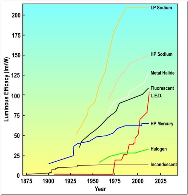
EFFICACY (LUMENS/WATT)
Luminous efficacy is a measure of how well a light source produces visible light. It is the ratio of luminous flux (LUMEN) to power (WATT).
The overall luminous efficacy of a source is the product of how well it converts energy to electromagnetic radiation,
and how well the emitted radiation is detected by the human eye. By calculation, the maximum possible efficacy is 683 lm/W.
|
STARTUP TIME
Some bulbs do not achieve their full light output immediately after starting. They require a period of time to reach full output.
This period is called the startup (warm-up or run-up) time.
|
RESTRIKE TIME
After a bulb has been on for a period of time and then extinguished, it cannot be immediately turned back on. Before the lamp can be turned back on,
the arc tube must have a chance to cool down or the lamp will not restart. This period of time is called the restrike time. Restrike times for
traditional probe-start MH lamps can take 15 minutes or longer, but restrike times for pulse-start MH lamps can be more than twice shorter.
|
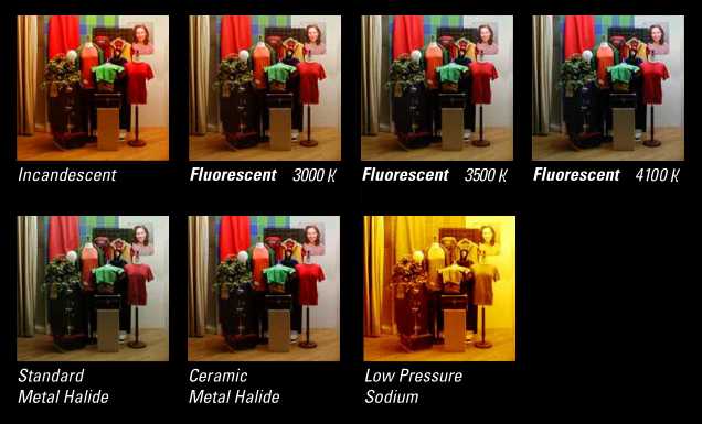
COLOR TEMPERATURE (CCT)
The actual color of a light source, also referred to as Correlated Color Temperature, measured in degrees Kelvin (K).
By convention, yellow-red colors (like the flames of a fire: 2700–3000 K) are considered warm, and blue-green colors (like light from an overcast sky: 3600–5500 K)
are considered cool. Cool light is preferred for visual tasks because it produces higher contrast than warm light. Warm light is preferred for living spaces because
it is more flattering to skin tones and clothing. A color temperature of 2700–3600 K is generally recommended for most indoor general and task lighting applications.
Color Temperature of Blue Sky is 10000K-30000K, Overcast sky is 7000K, Candle flame is 1800K.
Color Temperature is not an indicator of bulb surface temperature or heat dissipation.
|
COLOR RENDERING INDEX (CRI)
A measurement to rate a lamps accuracy to render an objects color on a scale of 0-100. The higher the CRI the more true to life colors appear,
as they would in natural daylight. CRI is related to color temperature, in that the CRI measures for a pair of light sources can only be compared
if they have the same color temperature
|
| Tip: Colors observed under a quartz halogen photoflood bulb (3,200K Color temperature and a perfect CRI) appear exactly the same as they do in sunlight.
|
TOUCHING A HALOGEN BULB SHORTENS ITS LifE
Halogen bulbs burn much brighter and produce much more heat than standard incandescent bulbs. When you touch a halogen bulb,
oil from your skin leaves a residue on the bulb glass surface. When the bulb is switched on and begins to get hot, much of the heat is dispersed
into the air around the bulb and carried away. However, when there is oil on the bulb, the oil begins to get heated as well. The amount of heat
generated is enough to cause the oil to boil. This hot spot puts a great deal of heat near the glass bulb and can cause the glass
in the hot spot to warp and stretch. This creates a weak spot in the glass bulb, which can break and thus shorten the life time.
POWER CALCULATIONS
Indicated bulb power (w) of lighting fixtures show the maximum power level of the bulb that can be used with that fixture.
Usually, you may use less power bulbs but using higher power bulb then indicated power may result in burning paint, melting parts, damaged transformer or fire.
Indicated transformer/ballast power is the maximum load a transformator/ballast can supply to the bulb(s) connected.
Long wires from transformer/ballast to the bulb also increase power consumption and should be taken into account when calculating.
There are three terms you will encounter when dealing with alternating current (AC) power:
1) Real Power, measured in KiloWatt (KW). Real power can perform work. Power company utility meters measure this quanity and charge for it.
2) Reactive Power, measured in KiloVolt-Amperes Reactive (KVAR). Unlike real power, it cannot perform work.
Reactive power is not a problem for a motor and is required for its operation. It is a problem for the electric utility company when they charge for KW only.
if two customers both use the same amount of real energy but one has a power factor of 0.5, then that customer also draws double the current. This increased
current requires the power company to use larger transformers, wiring and related equipment. To recover these costs, industrial customers are charged a price
premium for low power factors. Home users are not charged for this and utility meters in houses do not record it.
3) Apparent Power, measured in KiloVolt-Ampers (KVA). if you set two multimeters to measure current (A) and voltage (V) and multiply the readings,
you get apparent power in VA. To distinguish it from real power, VA is used instead of W.
In the case of resitive loads (like a heater or an electric stove element or a standard incandescent bulb), the current and voltage are in phase.
Real power equals apparent power and reactive power equals zero.
POWER FACTOR
The power factor is the ratio of Real Power (KW) to Apparent Power (KVA). if they are equal, then power factor equals 1. The power factor of a toaster or an ordinary
incandescent bulb is 1 (maximum). Devices with coils or capacitors (like pumps, fans and flourescent bulb ballasts) have power factors less than 1.
When the power factor is less than 1, the current and voltage are out of phase. This is due to energy being stored and released into inductors (motor coil)
on every AC cycle (usually 50/60 times per second). The power factor is lower when the induction motor is oversized and under-loaded.
The energy saving achieved by using condensers is the main reason why it is recommended to use high power
factor light fittings (compensated) that incorporate the necessary condensers for suitable power factor correction. Power factor correction makes sense for
commercial/industrial users who use large amounts of power.
|
COLOR APPEARANCE COMPARISON OF BULBS
|
PROGRESS OF BULB EFFICACY
|
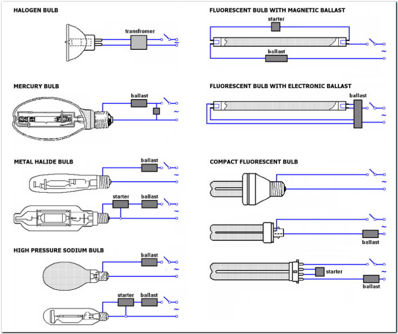
BULB CONNECTION DIAGRAMS
 |
|
|
 The most common fluorescent starter is called a "glow tube starter" (or just starter) and contains a small gas (neon, etc.) filled tube
and an optional radio frequency interference (RFI) suppression capacitor in a cylindrical aluminum (or plastic) can with a 2 pin base.
While all starters are physically interchangeable, the wattage rating of the starter should be matched to the wattage rating of the fluorescent
tubes for reliable operation and long life. It is like a time-delay switch that is closed at start. (meaning, allows the current to pass at start)
The most common fluorescent starter is called a "glow tube starter" (or just starter) and contains a small gas (neon, etc.) filled tube
and an optional radio frequency interference (RFI) suppression capacitor in a cylindrical aluminum (or plastic) can with a 2 pin base.
While all starters are physically interchangeable, the wattage rating of the starter should be matched to the wattage rating of the fluorescent
tubes for reliable operation and long life. It is like a time-delay switch that is closed at start. (meaning, allows the current to pass at start)
When you turn on a fluorescent tube, the current passing through starter heats the filaments at the ends of the tube,
and they create a cloud of electrons inside the tube. The starter opens after a second or two, cutting the current to the filaments.
When it opens, the current across the tube allows the stream of electrons to flow across the tube and ionize the mercury vapor.
Without the starter, a steady stream of electrons is never created between the two filaments, and the bulb flickers. Without the ballast,
the arc is a short circuit between the filaments, and this short circuit contains a lot of current. The current either vaporizes the filaments
or causes the bulb to explode.
• Switch Start
This is the simplest circuit and therefore most economical to purchase where the capital cost of the installation has to be kept to a minimum.
The circuit consists of a magnetic ballast, a radio frequency interference (RFI) suppression capacitor and a glow starter canister. The starter switch closes, permitting a current to flow
through each electrode. The starter switch rapidly heats up, opening the switch, and triggering the supply voltage across the arc tube,
initiating the discharge. No auxiliary power is applied across the electrodes during operation. It is very important to replace defective starters
to prevent gear overheating and damage.
• Electronic Start
This uses an electronic starting device, with a magnetic ballast, instead of the conventional starter switch and provides flicker free
bulb starting. The electronic starter gently warms the bulb for fractions of a second before starting, extending the bulb life by up to 50%, depending
on switching frequency. Lumen maintenance is also improved as bulb end blackening is reduced. The electronic starter also automatically switches off a
failed bulb thus preventing troublesome bulb flicker and flashing. Flicker can lead to ballast burnout.
• Electronic Start, High Frequency
This circuit uses the latest electronic technology to give substantial benefits to the user. It provides all the benefits of electronic start -
flicker free soft starting, extended bulb life, improved lumen maintenance and automatic shutdown of failed bulbs. In addition the bulb is driven
at high frequency, offering an instant energy saving of approximately 20% over the other circuits, using exactly the same bulbs. High frequency
circuits run at near unity power factor, reducing VA load and therefore cutting the electricity costs of users on maximum demand tariffs. Additionally,
the light is perfectly flicker free. Flicker free lighting greatly reduces the incidence of headaches and eye strain, eliminates distractions and thus
improves workplace quality and productivity. For production areas, high frequency lighting prevents the dangerous stroboscopic effects often experienced
with switch start and electronic start circuits, when using rotating machinery. High frequency lighting is also completely silent in operation.
• Electronic Start, Digital High Frequency Regulating
This circuit has all the advantages of high frequency, but with the added benefit of being able to dim and brighten (regulate) the bulbs. This
circuit is therefore used for lighting and energy management systems. As bulbs are dimmed, either manually or automatically, such as in response
to an increase in daylight detected by a photocell, the ballast energy consumption is reduced. Therefore, further energy saving cost benefits can
be realised. Digital regulating ballasts also provide precision control of light output, superior to that experienced with conventional analogue
regulating ballast types.
• Instant Start
An instant start ballast starts bulbs without heating the cathodes at all by using high voltage (around 600 V). It is the most energy
efficient type, but gives the least number of starts from a bulb as emissive oxides are blasted from the cold cathode surfaces each time
the bulb is started. This is the best type for installations where lamps are not turned on and off very often.
• Rapid Start
A rapid start ballast applies voltage and heats the cathodes simultaneously. Provides superior bulb life and more cycle life, but uses
slightly more energy as the cathodes in each end of the bulb continue to consume heating power as the bulb operates. A dimming circuit can be
used with a dimming ballast, which maintains the heating current while allowing bulb current to be controlled.
• Preheat/Programmed Start
A programmed-start ballast is a more advanced version of rapid start. This ballast applies power to the filaments first, then after a short delay
to allow the cathodes to preheat, applies voltage to the bulbs to strike an arc. This ballast gives the best life and most starts from bulbs,
and so is preferred for applications with very frequent power cycling such as vision examination rooms and restrooms with a motion detector switch.
|
|
|
An electrical ballast is a device intended to limit the amount of current in an electric circuit. All gas discharge bulbs,
including fluorescent bulbs, require a ballast to operate. The ballast provides a high initial voltage to initiate
the discharge, then rapidly limits the bulb current to safely sustain the discharge.
MAGNETIC BALLASTS (KVG - Konventionelles Vorschaltgerät)
 Electromagnetic ballasts are designed to condition the 50/60 Hz input voltage to the electrical requirements of the bulbs. A magnetic ballast
alters the voltage, but not the frequency. Thus, the bulb voltage crosses zero 100/120 times each second, resulting in 100/120 Hz light output
oscillations. This results in about ~30% flicker for standard halophosphor bulbs, operated at 50/60 Hz. The flicker is generally not noticeable
but may cause adverse effects, such as eyestrain and headache.
One characteristic of iron-cored electromagnetic ballasts operating at 50/60 Hz, is the generation of audible noise. This noise is
generated by the vibration of laminations in the electromagnetic field that transforms the voltage and current. Noise may increase by high
temperatures, and may be amplified by certain luminaire designs. The best ballasts use high quality materials and workmanship to reduce noise.
Noise is rated A, B, C, or D. An "A" rated ballast will hum softly; a "D" rated ballast will make a loud buzz. Magnetic ballasts requires a
bulb starter and a capacitor.
Electromagnetic ballasts are designed to condition the 50/60 Hz input voltage to the electrical requirements of the bulbs. A magnetic ballast
alters the voltage, but not the frequency. Thus, the bulb voltage crosses zero 100/120 times each second, resulting in 100/120 Hz light output
oscillations. This results in about ~30% flicker for standard halophosphor bulbs, operated at 50/60 Hz. The flicker is generally not noticeable
but may cause adverse effects, such as eyestrain and headache.
One characteristic of iron-cored electromagnetic ballasts operating at 50/60 Hz, is the generation of audible noise. This noise is
generated by the vibration of laminations in the electromagnetic field that transforms the voltage and current. Noise may increase by high
temperatures, and may be amplified by certain luminaire designs. The best ballasts use high quality materials and workmanship to reduce noise.
Noise is rated A, B, C, or D. An "A" rated ballast will hum softly; a "D" rated ballast will make a loud buzz. Magnetic ballasts requires a
bulb starter and a capacitor.
ELECTRONIC BALLASTS (EVG - Elektronisches Vorschaltgerät)
 Electronic ballasts usually change the frequency of the power from the standard mains frequency of 50/60 Hz to 20,000 Hz or higher, substantially
eliminating the stroboscopic effect of flicker. In addition, because more gas remains ionized in the arc stream, the bulbs actually operate at
about 9% higher efficiency above approximately 10 kHz. Bulb efficiency increases sharply at about 10 kHz and continues to improve until
approximately 20 kHz. Because of the higher efficiency of the ballast itself and the improvement of bulb efficiency by operating at a higher
frequency, electronic ballasts offer higher system efficiency.
Electronic ballasts usually change the frequency of the power from the standard mains frequency of 50/60 Hz to 20,000 Hz or higher, substantially
eliminating the stroboscopic effect of flicker. In addition, because more gas remains ionized in the arc stream, the bulbs actually operate at
about 9% higher efficiency above approximately 10 kHz. Bulb efficiency increases sharply at about 10 kHz and continues to improve until
approximately 20 kHz. Because of the higher efficiency of the ballast itself and the improvement of bulb efficiency by operating at a higher
frequency, electronic ballasts offer higher system efficiency.
Well-designed electronic high-frequency ballasts should emit no perceptible hum. All electronic ballasts are "A" rated for sound.
DIGITAL HIGH-INTENSITY DISCHARGE BALLASTS (DHID)
A DHID bulb ballast is an electronic ballast that uses a microprocessor to control and regulate a High-Intensity Discharge (HID) bulb.
The firmware can provide control algorithms to supply varying bulb currents during start-up and during bulb operation. The firmware
controls the initial voltage strike to the bulb to start it and then controls current in the bulb for the most efficient burning of the bulb.
DIMMING FLUORESCENT BULBS
Unlike incandescent bulbs, fluorescent bulbs cannot be properly dimmed with a simple wall unit used for incandescent bulbs. For a fluorescent bulb
to be dimmed over a full range without a reduction in bulb life, its electrode heater voltages must be maintained while the bulbs arc current is
reduced. As such, bulbs operated in rapid start mode are the only fluorescent bulbs suitable for wide-range dimming applications. The power required
to keep electrode voltage constant over all dimming conditions means that dimming ballasts will be less efficient when operating bulbs at dimmed levels.
Dimming ballasts are available in both magnetic and electronic versions, but there are distinct advantages to using electronic dimming ballasts.
To dim bulbs, magnetic dimming ballasts require control gear containing expensive high power switching devices that condition the input power
delivered to the ballasts. This is economically viable only when controlling large numbers of ballasts on the same branch circuit. In addition,
luminaires must be controlled in large zones that are determined by the layout of the electrical distribution system. Since the distribution
system is fixed early in the design process, control systems using magnetic dimming ballasts are inflexible and are unable to accommodate changes
in usage patterns.
Dimming of electronically-ballasted bulbs is accomplished within the ballast itself. Electronic ballasts alter the output power to the bulbs by a
low-voltage signal into the output circuit. High power switching devices to condition the input power is not required. This allows control of one
or more ballasts independent of the electrical distribution system. With dimming electronic ballast systems, a low voltage control network can be
used to group ballasts together into arbitrarily-sized control zones. This control network may be added during a building renovation or a lighting
retrofit. It is less costly to modify the size and extent of lighting zones by reconfiguring low voltage wiring when usage patterns change. Low
voltage wiring is also compatible with photocells, occupant sensors, and energy management system (EMS) inputs.
BALLAST FACTOR
One of the most important ballast parameters for the lighting designer is the ballast factor. The ballast factor is needed to determine
the light output for a particular bulb-ballast system. Ballast factor is a measure of the actual lumen output for a specific bulb-ballast system
relative to the rated lumen output measured with a reference ballast under ANSI test conditions (open air at 25°C-77°F). An ANSI ballast for
standard 40w F40T12 bulb requires a ballast factor of 0.95; the same ballast has a ballast factor of 0.87 for 34w energy saving F40T12 bulb.
However, many ballasts are available with either high (conforming to the ANSI specifications) or low ballast factors (70 to 75%). It is
important to note that the ballast factor value is not simply a characteristic of the ballast, but of the bulb-ballast system. Ballasts
that can operate more than one type of bulb (e.g. the 40w F40 ballast can operate either 40w F40T12, 34w F40T12, or 40w F40T10 bulbs) will
generally have a different ballast factor for each combination (e.g. 95%, <95%, and >95%, respectively).
Ballast factor is not a measure of energy efficiency. Although a lower ballast factor reduces bulb lumen output, it also consumes proportionally
less input power. As such, careful selection of a bulb-ballast system with a specific ballast factor allows designers to better minimize energy
use by "tuning" the lighting levels in the space. For example, in new construction, high ballast factors are generally best, since fewer luminaires
will be required to meet the light level requirements. In retrofit applications or in areas with less critical visual tasks, such as aisles and hallways,
lower ballast factor ballasts may be more appropriate.
To avoid a drastic reduction in bulb life low ballast factor ballasts ( <70% ) should operate bulbs in rapid start mode only. This is particularly
relevant for 32w F32T8 bulbs operated at high frequency.
|
|
|
Some lighting products are made to work on 12V (low voltage) instead of 230V (mains voltage).
In order to connect a 12V bulb, it must first be connected to a transformer, which transforms the 230V mains voltage to the required 12V,
which is safe to touch.
MAGNETIC TRANSFORMERS
 In a magnetic low-voltage transformer, two coils of wire, the primary and secondary coil, are used. The primary coil carries the input or
high voltage and creates a magnetic flow, which induces a current in the secondary coil. Since there are more windings in the primary coil
than in the secondary, the secondary coil has a lower voltage. The exact output voltage depends on the number of windings in the two coils.
They operate at standard low frequencies (5O/6O Hz). They offer very reliable operation, are very durable and able to withstand power quality
problems. Since magnetic transformers operate at low frequencies, they will not cause any interference and will experience less vo1tage drop over
a long distance compared to high frequency electronic transformers.
In a magnetic low-voltage transformer, two coils of wire, the primary and secondary coil, are used. The primary coil carries the input or
high voltage and creates a magnetic flow, which induces a current in the secondary coil. Since there are more windings in the primary coil
than in the secondary, the secondary coil has a lower voltage. The exact output voltage depends on the number of windings in the two coils.
They operate at standard low frequencies (5O/6O Hz). They offer very reliable operation, are very durable and able to withstand power quality
problems. Since magnetic transformers operate at low frequencies, they will not cause any interference and will experience less vo1tage drop over
a long distance compared to high frequency electronic transformers.
There are two types of magnetic transformers: stack laminated and toroidal. The stack laminated are square and the toroidal are circular
shaped. Stack laminated transformers are long-lived, lasting 15-20 years. Toroidal transformers last even longer and are very quiet when
compared to either the stack laminated magnetic transformer or the electronic transformer. Both types of magnetic transformers are rated at
higher operating temperatures than electronic transformers. Depending on quality (or by time) stack laminated transformers may create buzzing noise.
ELECTRONIC TRANSFORMERS
 The electronic transformer is different from a toroidal transformer in that it uses an electronic inverter to convert mains frequency AC 50Hz
into high frequency AC, between 10kHz and 100 kHz depending on the transformer. An internal magnetic transformer then reduces the output voltage
to 12V AC at 10- 100 kHz.
Contain a small transformer and an inverter. The inverter changes the frequency at which the alternating current into the transformer changes
directions. In a home low-voltage use, it typically changes the frequency of the 230V power outlet from 50/60 hertz (or cycles per second) to
10,000-100,000 hertz. Internal magnetic transformer then reduces the output voltage to 12V AC at 10,000-100,000 hertz. The higher the frequency
of the voltage, the smaller the transformer needed to provide the required output voltage.
They are very compact and much smaller and lighter than their magnetic counterparts. They provide built in protection against electrical
shorts applied at the outputs and to the lighting system. In order for electronic transformers to operate properly, the output must be loaded to a
minimum of typcally 50% of the rated wattage of the transformer. Any output load below 50% may result in bulbs flickering and premature bulbs
burning out. Since electronic transformers operate at much higher frequencies, most standard voltmeters or ampmeters intended for 50/60hz type
measurements cannot be used to accurately measure the outputs of these transformers.
The electronic transformer is different from a toroidal transformer in that it uses an electronic inverter to convert mains frequency AC 50Hz
into high frequency AC, between 10kHz and 100 kHz depending on the transformer. An internal magnetic transformer then reduces the output voltage
to 12V AC at 10- 100 kHz.
Contain a small transformer and an inverter. The inverter changes the frequency at which the alternating current into the transformer changes
directions. In a home low-voltage use, it typically changes the frequency of the 230V power outlet from 50/60 hertz (or cycles per second) to
10,000-100,000 hertz. Internal magnetic transformer then reduces the output voltage to 12V AC at 10,000-100,000 hertz. The higher the frequency
of the voltage, the smaller the transformer needed to provide the required output voltage.
They are very compact and much smaller and lighter than their magnetic counterparts. They provide built in protection against electrical
shorts applied at the outputs and to the lighting system. In order for electronic transformers to operate properly, the output must be loaded to a
minimum of typcally 50% of the rated wattage of the transformer. Any output load below 50% may result in bulbs flickering and premature bulbs
burning out. Since electronic transformers operate at much higher frequencies, most standard voltmeters or ampmeters intended for 50/60hz type
measurements cannot be used to accurately measure the outputs of these transformers.
Electronic transformers may cause interference with appliances such as TVs and radios. if interference is a problem, a line filter may be installed
either at the transformer or at the appliance input. They last about 5-6 years, 3-4 times less then magnetic ones.
They are also heat-sensitive; warm environments will reduce their lifespan further.
Electronic units are more vulnerable to line surges and transients so can be less reliable, fluctuations in voltage and high current generate
quite a bit of heat that stresses electronic components.
Some transformers may have a minimum load to work at optimum performance. Loading them less may increase the output voltage and
decrease bulbs life.
A transformer may be loaded to 80% of its maximum output wattage. But, it can never be loaded over 100%.
Example: You may connect 3 bulbs of 20w + 20w + 50w = 90w to a 100w transformer. But,
you should never connect 20w + 20w + 20w + 50w = 110w to a 100w transformer.
A transformer connected to the mains without a load still consumes energy, it may reach about 0.5% of its power.
A quality transformer will have specifications like RFI (Radio Frequency Interference) suppression, Short circuit protection, Current overload
protection, Thermal overload protection.
True power calculation of a transformer: P (true power, Watt) = S (apperent power, VA) x |cos φ| (power factor)
DIMMING
Some low voltage bulbs can be dimmed like main voltage bulbs, but the transformer must be capable of dimming. if not capable, the transformer
may be damaged by the dimmer.
- Mains Dimming
This method of dimming is most commonly used for low voltage transformers typically used for halogen lamps. Rarely used for LED fittings.
No control cable is required.
Mains Dimming a low voltage transformer may cause voltage drop even when the dimmer is set at full output. Lower voltage from the transformer results
in less light output from the fixtures. You may use a magnetic low voltage dimmer for magnetic transformers and an electronic low voltage dimmer for
electronic transformers.
- 1-10V
Control interface that can adjust light with analogue voltage signal in the range 1-10V. Simple and reliable solution to adjust light
intensity for personal needs. It requires a separate control cable to be run from the controller to each fittings driver.
- DALI
Control interface used to manage appliances and devices. It ensures precise intensity management and satisfies lighting requirements
surpassing 1-10V interface solutions. It is cost effective, flexible and has simple wiring. It requires a control cable which can be run between many fittings.
- DMX
Control interface used for colour programmable fittings. The DMX signal is generated by a lighting control system and requires dedicated cabling
between the controller and driver. DMX is generally used with professionally designed lighting control systems.
Transformer to lamp low voltage cable lenght is limited:
Low voltage lighting means carrying higher current for the same power. To get 300 watts from 230V mains voltage cable carries 1.8A current, but
if you use 12V line it carries 34.5A.
230 Volts x 1.8 Amperes = 300 watts
12 Volts x 34.5 Amperes = 300 watts
Cable loses voltage according to its length. The lower the voltage the bigger the loss. On low voltage/high current connections, the voltage can
drop over a long distance and your lights will not be as bright. For this reason, transformer-lamp distance should be kept minimum
to decrease the lenght of low voltage cable. The max.lenght of a cable from transformer to lamp may be increased by increasing the cable wire section.
Wire sections (mm2) to be used depending on the cable lenght (12V with max.3% loss at the end)
|
|
|
For the purposes of installing electrical equipment, a bathroom is divided into zones. The criteria for each zone is based on the risk of electric shock.
The zones relate to the IP rating of products and where they can be safely installed. A fixture with a higher IP rating then indicated can also be used.
Zone 1 is assumed to have an enclosure door and side panels.
| Zone 0 |
IP68 (submersible) - The ultimate in water-tight fittings. Suitable for saunas, steam rooms or to be mounted underwater down to 9 metres. |
| Zone 1 |
IP65 (jetproof) - Should be fitted where the fitting may be subjected to a jet of water, for example from a shower handset |
| Zone 2 |
IP44 (splashproof) - Should be fitted wherever the fitting may be splashed. Anywhere within 0.6 metres of a basin or similar water source. |
| Zone 3 |
IP20 - For all other areas where jets or splashes of water will not occur. Although there is no IP limit, it is better to use a fixture with a cover
diffuser over the bulb.
IP44 - In case of poor ventilation or possibility of high condensation.
IP65 - In case of water jets being used for cleaning purposes in zones 2 and 3. |
|
|
|
Wikipedia
Philips
Osram
GE Lighting
Disclaimer: The information contained in this page have been obtained from sources believed to be reliable.
|
|
|
|
 eu
eu
 ru
ru 0
0

 BG - Болгария
 CZ - Чехия
 GR - Греция
 WW - Всемирной
 EN - English